

Precast L-shaped RCC units · Trilok Infratech, Surat · est. 2005

Earth Retaining Wall

One-piece L units · 8 standard heights · L 2000 mm

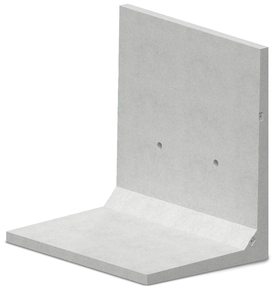
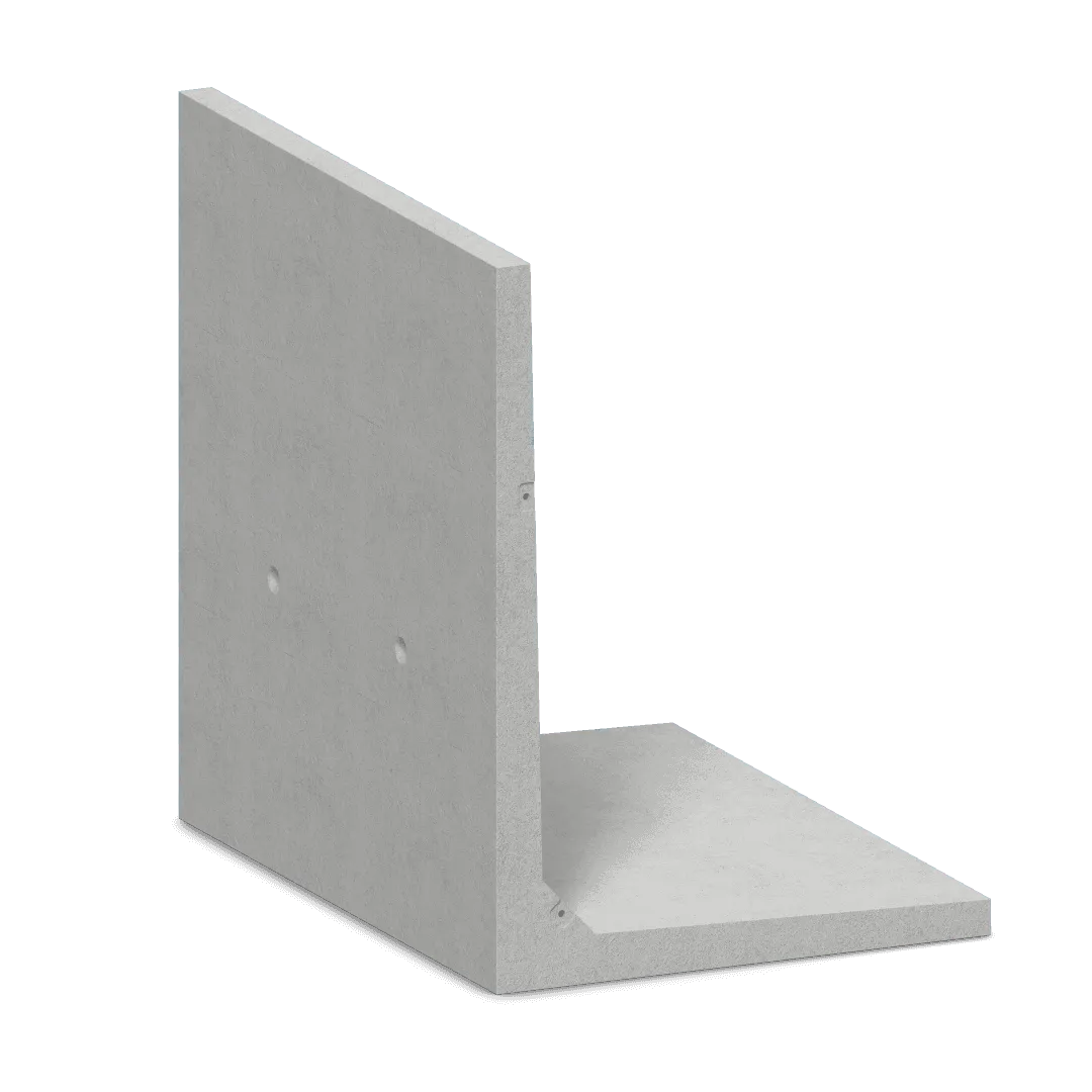
An earth retaining wall holds back soil where the ground level changes, resisting the sideways pressure of the earth behind it. Trilok Infratech's precast earth retaining wall is a one-piece L-shaped RCC unit, a vertical stem cast with a base slab, made in M50–M75 concrete, 2000 mm long, in 8 standard heights from 600 to 2500 mm.

Earth retaining wall: precast RCC L-shaped unit, a vertical stem cast with a base slab
01 Standard heights
08
02 Wall height H
600–2500 mm
03 Base width B
680–1750 mm
04 Unit length L
2000 mm
05 Grade
M50–M75
06 Draining hole
Ø70/75
Scroll
[01]How it works

How an earth retaining wall holds the ground

Four things happen behind every retaining wall. Scroll through them — the drawing builds as you go.

  1. Level change

    The ground changes level

    Cut a road, a plot or a channel into sloping ground and the soil on the high side wants to slump back to a gentler, natural slope. A retaining wall holds that soil upright instead, so you get two level surfaces and a vertical face between them.

  2. Earth pressure

    Soil pushes sideways — hardest at the bottom

    Retained soil presses on the back of the wall, and the push grows with depth, so the bottom carries the most. Engineers estimate this lateral earth pressure from the soil's weight and internal friction; the published design basis takes γs = 19 kN/m³ and φ = 30°.

    • γs = 19 kN/m³
    • φ = 30°
  3. Load + water

    Loads and water push harder

    Anything standing on the retained ground adds to the push — the design basis allows an overburden load q = 10 kN/m². Water trapped behind a wall adds its own pressure, which is why every standard height has a Ø70/75 draining hole through the stem.

    • q = 10 kN/m²
    • Ø70/75 draining hole
  4. The L unit

    The L shape turns the push into grip

    The base slab runs back under the retained soil, so the soil's own weight presses it down and helps stop the unit tipping. The published design basis checks sliding (Fs ≥ 1.5) and keeps the resultant force within the middle third of the base (|e| ≤ B/6).

    • Fs ≥ 1.5
    • |e| ≤ B/6
front groundretained groundnatural slopewaterPq = 10 kN/m²L UNITWsoil on the base|e| ≤ B/6Fs ≥ 1.5
Schematic, not to scale. Values are the published design basis; site-specific checks are for the project engineer.
[02]The unit

Precast RCC retaining wall, one L unit

Stem and base cast as one piece in M50–M75 concrete — 8 standard heights from 600 to 2500 mm, every unit 2000 mm long. The full dimension table, drawings and 3D configurator are on the technical sheet.

Precast RCC earth retaining wall unit (L-shaped)
Precast RCC earth retaining wall L unit in three-quarter view: the tall stem rising from the base slab
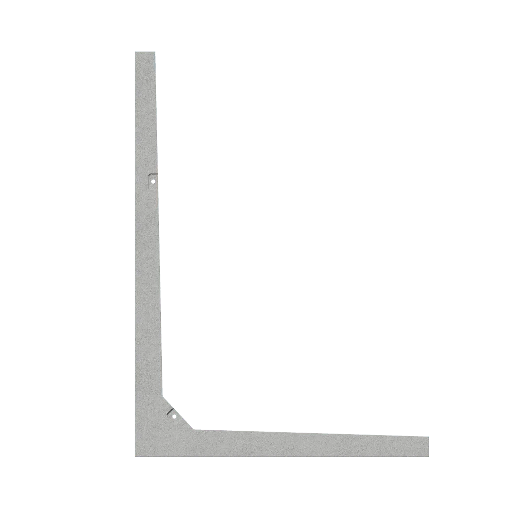
Precast earth retaining wall L unit, side view: stem and base slab meeting at a haunched corner

Earth Retaining Wall

Structurally robust precast retaining wall system designed to resist lateral soil pressure in embankments, highways, basements, and sloped terrain.

8 standard heights · H 600 to 2500 mm

Size range
H 600 to 2500 mmwall height
Standard heights
08
Unit length L
2000 mm
Concrete grade
M50–M75
Base width B
680–1750 mmgrows with height
Draining hole
Ø70/75centre at h = 300–900 mm

Durable Material

High-strength RCC units engineered to resist lateral earth pressure, moisture, and long-term ground movement. Cast in M50–M75 concrete.

Efficient Design

One-piece L units, 2000 mm long, placed side by side on a continuous foundation — 8 standard heights from 600 to 2500 mm, the base slab widening from 680 to 1750 mm as the wall gets taller.

Dual Application

Suitable for highway embankments, basement perimeters, sloped landscaping, and industrial plot boundaries.

Applications

  • Soil erosion prevention
  • Retaining soil at culverts, underpasses and bridges
  • Stability in sloped soil
  • Landscaping
[03]By the numbers
  • M50–M75

    Concrete grade

    RCC, every unit

  • 2000mm

    Unit length L

  • 08

    Standard heights

  • 600–2500mm

    Wall height H

  • 680–1750mm

    Base width B

    grows with height

  • 300–900mm

    Draining hole height h

    Ø70/75 hole through the stem

[04]Anatomy

Anatomy of an L-shaped precast retaining wall unit

One piece of M50–M75 RCC: a vertical stem cast with a base slab that runs back under the retained soil. Pick a height — the section is drawn from the published dimensions, all 8 heights to one scale.

Height H (mm)

600800100012001800200022502500t3 100t4 140g 150t2 140h 800 · Ø70/75t1 100H 2000B 1450front groundretained soil
Section of the H 2000 mm unit, drawn from the published dimensions (H, B, t1–t4, g, h) with the typical foundation detail. All 8 heights are outlined behind it at the same scale. The foundation drawing embeds the base more than 0.15H below the front ground level; the value shown is 0.15H computed for the selected height.

Height H
2000 mm
Base width B
1450 mm
Stem t1 → t2
100 → 140 mm
Base t3 → t4
100 → 140 mm
Haunch g
150 mm
Draining hole h · Ø70/75
800 mm
Unit length L
2000 mm
Profile
Tapered
Embed base (0.15H) · computed
> 300 mm

Wall-run planner

10units of H 2000 mm≈ wall length ÷ L 2000 mm

Estimate only: wall length ÷ 2000 mm unit length, rounded up. Corners, ends and site details change the count — your quotation confirms it.

Uniform profile · H 600–1200

Stem and base keep one thickness (t1 = t2, t3 = t4): 70 mm at H 600, 80 mm at H 800, 90 mm at H 1000 and 100 mm at H 1200.

Tapered profile · H 1800–2500

The stem thickens from t1 at the top to t2 at the base, and the base slab from t3 at the heel to t4 at the stem (100 → 140 mm and 100 → 170 mm), where a taller wall is pushed hardest.

What the letters mean

H
Overall height of the unit, from the underside of the base slab to the top of the stem (the table's HEIGHT column).
B
Overall base width, from the exposed front face of the stem to the far (heel) end of the base slab.
t1
Stem (vertical wall) thickness at the top.
t2
Stem thickness at the bottom, where it meets the base (dimensioned at base level, excluding the haunch).
t3
Base slab thickness at its free (heel) end.
t4
Base slab thickness next to the stem, at the stem–base junction (excluding the haunch).
g
Size of the chamfered haunch in the inside corner between stem and base, drawn with equal horizontal and vertical legs g.
h
Height of the centreline of the Ø70/75 draining hole through the stem, measured from the underside of the base.
L
Unit length along the wall (2000 mm for every size). Not shown on the section drawings.
[05]Heights

Earth retaining wall heights & dimensions

Set the overall wall height H from your drawings — the smallest standard unit that covers it lights up in the dimension table. H runs from the underside of the base; the base sits more than 0.15H below the front ground, so the exposed face is lower than H.

Size explorer

Set the overall wall height H you need — the smallest standard size that covers it lights up below.

Precast earth retaining wall dimensions by height (mm)
Height HBase width Bt1 stem topt2 stem baset3 heelt4 at stemg haunchHole centreLength L
600680707070701003002000
800760808080801004002000
1000850909090901005002000
12009701001001001001206002000
180013301001401001401508002000
200014501001401001401508002000
225016001001701001701809002000
250017501001701001701809002000
All dimensions in mm. Note : Customized sizes available for mass quantity.

No standard heights between 1200 and 1800 mm — a wall that needs an H in that range uses the H 1800 unit. H is the overall height; the retained (exposed) height is lower (base embedded more than 0.15H).

[06]Design basis

How the wall stays standing

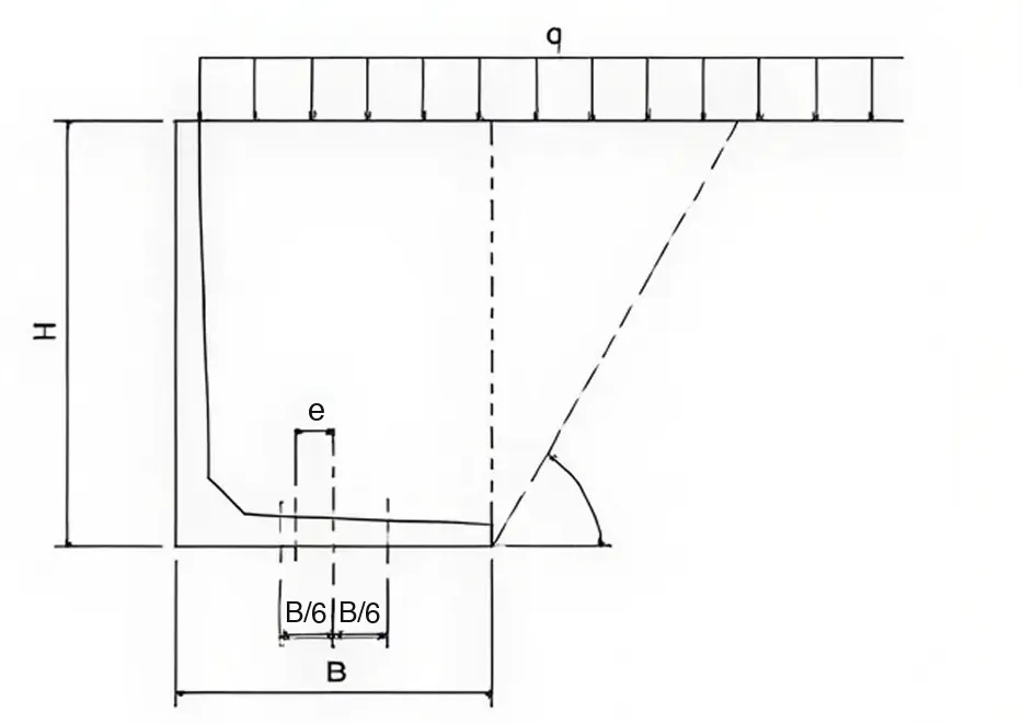
A retaining wall can fail by sliding forward, tipping over, or overloading the ground beneath it. The published design basis sets the first two checks — Fs ≥ 1.5 against sliding and |e| ≤ B/6 against overturning — on the soil and load values below; the bearing capacity of your ground is a site-specific check.

Earth retaining wall design basis (as published) and what each parameter means
ParameterPublished valueWhat it means
Reinforced Concrete Unit Weightγc = 24.5 kN/m³The weight of reinforced concrete used in the calculations — the unit's own weight helps resist sliding and overturning.
Unit Weight of soilγs = 19 kN/m³The weight of the retained soil assumed in design. Heavier soil pushes harder, but the soil resting on the base slab also helps hold the unit down.
Angle of internal friction of soilφ = 30°How strongly the soil grains lock together. A lower angle means more sideways pressure, so the backfill should match the design assumption.
Overburden loadq = 10 kN/m²A uniform load on the retained ground surface behind the wall. Heavier loads close to the wall — vehicles, stockpiles, buildings — need a site-specific check.
Sliding safety factorFs ≥ 1.5The forces resisting sliding along the base must be at least 1.5 times the forces pushing the wall forward.
Eccentricity (for overturning)|e| ≤ B/6The resultant force must land within the middle third of the base width B, so the whole base stays in contact with the foundation.
Design basis as listed in the company brochure. It is not a load rating — share your site conditions and loads with the enquiry; site-specific checks are for the project engineer.
Design check diagram for the precast earth retaining wall: load q, height H, base width B, eccentricity e
Design check diagram: overburden load q on the retained soil, wall height H, base width B, and eccentricity e of the resultant kept within B/6 of the base centre.
[07]Drainage

Drainage: why the draining holes matter

Poor drainage is one of the most common reasons retaining walls get into trouble. Saturated soil pushes harder, and water trapped behind a wall adds pressure of its own — so the water needs a way out.

  1. Ø70/75

    A draining hole through every stem

    Each standard height has a Ø70/75 draining hole through the stem. Its centreline sits at height h above the underside of the base — from 300 mm on the smallest unit to 900 mm on the tallest.

  2. Filter

    A filter that keeps the soil in

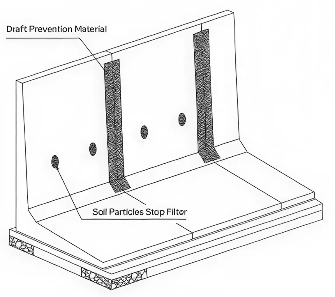
    On the soil side, a soil particles stop filter covers the draining hole: water passes through, the soil stays behind, and the hole stays clear.

  3. Joints

    Strips over every joint

    Adjacent 2000 mm units sit on one continuous foundation, with draft prevention material strips fixed over the joints between them on the soil side.

Keep the backfill behind the stem free-draining and the draining holes clear, so water can always reach them.

Isometric foundation detail of the precast earth retaining wall: adjacent L units with joint strips and a stop filter
Typical foundation detail (isometric, soil/heel side): adjacent units on a continuous foundation, with draft prevention material strips over the joints between units and a soil particles stop filter (its leader points to a draining hole).
[08]Applications

Where earth retaining walls are used

Wherever the ground level changes — from erosion control to the embankments beside culverts and bridges.

[09]Installation

How a precast retaining wall is installed

Units go in side by side on a continuous foundation — the drawing builds with each step.

Retained soilFilter + draining holeL unit, 2000 mm long20 mm bedding mortar100 mm foundation concreteExcavation150 mm crushed stone
Typical foundation detail (section): unit on bedding mortar (20) over foundation concrete (100) and a crushed stone foundation (150), the foundation projecting 100 mm beyond B on each side; base embedded more than 0.15H below the front ground level; draining hole through the stem. Schematic · not to scale
  1. Step 1: Set out and excavate

    Mark the wall line and dig to the level on your drawings — the base must end up more than 0.15H below the finished ground in front of the wall.

  2. Step 2: Crushed stone foundation

    Lay and compact the crushed stone foundation (150 mm), 100 mm wider than the base on each side.

  3. Step 3: Foundation concrete

    Cast 100 mm of foundation concrete over the stone, true to line and level — it carries every unit along the run.

  4. Step 4: Bedding mortar

    Spread a 20 mm bed of mortar where each unit will sit, so the base bears evenly.

  5. Step 5: Place the units side by side

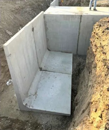
    Lift each 2000 mm L unit into place — stem to the front, base slab under the soil to be retained — and line it up tight against the last one.

  6. Step 6: Joint strips and filter

    On the soil side, fix the draft prevention material strips over the joints and the soil particles stop filter at each draining hole.

  7. Step 7: Backfill and restore

    Backfill behind the stem in compacted layers with the material your engineer specifies, keep the draining holes clear, then restore the ground in front over the base.

General sequence for guidance only — always follow your project drawings and the engineer's specification.

[10]Types of retaining walls

Types of retaining walls — where the L unit fits

Retaining walls hold soil in different ways. A precast L-shaped unit is a cantilever wall, cast in the factory instead of on site.

Types of retaining walls and where a precast L-shaped earth retaining wall fits
Type of wallHow it holds the soilTypically built from
Precast L-shaped unit (Trilok Infratech ERW)Cantilever: the stem resists the push, the soil on the base slab holds it downFactory-cast RCC in M50–M75, 8 standard heights 600–2500 mm, 2000 mm long
Gravity wallIts own heavy mass resists the soilMass concrete or stone masonry
Cast-in-situ cantilever (L / inverted T)Same principle as the L unit, formed and poured at siteRCC cast in place
Counterfort wallA cantilever wall stiffened by triangular cross-walls on the soil side, used for taller wallsRCC, usually cast in place
Crib wallInterlocking members form cells filled with granular material that act as a gravity massPrecast concrete or timber members
Segmental block wallSmall units laid in courses, often tied back with geogrid layersDry-laid concrete blocks
Gabion wallHeavy, free-draining stone baskets act as a gravity massWire-mesh baskets filled with stone
Reinforced soil (MSE) wallReinforcement layers in compacted fill turn the soil block itself into the wallGeogrid or strips with a facing
Sheet pile / anchored wallEmbedment below ground — and anchors where needed — resist the pushSteel or concrete sheet piles, ground anchors
General overview — the right type depends on height, soil, water, loads and access. The project engineer decides.
[11]Precast vs cast-in-situ

Precast or cast on site?

A general comparison of the two ways to build an RCC retaining wall.

Precast L-shaped retaining wall vs cast-in-situ retaining wall (general comparison)
AspectPrecast L-shaped unitsCast-in-situ wall
Where it is castIn moulds at the factory, cured in the yard before deliveryFormed, poured and cured in place
Work at siteFoundation, placing the units side by side, joints, backfillFormwork, steel fixing, pouring, curing, stripping — then backfill
Weather and curingCuring happens in the yard, away from the siteDepends on site weather and curing time
Equipment at siteA crane or lifting equipment to place the unitsFormwork, concrete supply and vibrators
Heights and shapes8 standard heights, 600–2500 mm; customized sizes available for mass quantity.A wider range of heights and shapes, designed for the site
ConcreteM50–M75 grade RCCAs specified for the project
General comparison — the right choice depends on height, quantity, site access and programme.
[12]Cost

Retaining wall cost: what affects it

We quote every job on its heights, length and scope — these are the things that move the number.

  1. Wall height

    Taller units are bigger in every direction: the base widens from 680 to 1750 mm and the stem thickens at the bottom (t2 70–170 mm).

  2. Length of wall

    Run length ÷ 2000 mm = the number of units. Corners and ends add detail.

  3. Quantity and custom heights

    Customized sizes available for mass quantity.

  4. Foundation, drainage and backfill

    Crushed stone, foundation concrete and bedding mortar under every unit (150 / 100 / 20 mm in the typical detail), plus filters, joint strips and free-draining backfill.

  5. Delivery and lifting

    Distance from the factory in Surat, truck loads and crane access at site.

[13]FAQ

Earth retaining wall questions

  1. An earth retaining wall holds back soil where the ground level changes, resisting the sideways pressure of the earth behind it. Trilok Infratech's precast earth retaining wall is a one-piece L-shaped RCC unit, a vertical stem cast with a base slab, made in M50–M75 concrete, 2000 mm long, in 8 standard heights from 600 to 2500 mm.

  2. An L-shaped (cantilever) retaining wall has a vertical stem and a base slab that runs back under the retained soil. The stem resists the sideways push of the soil, and the weight of the soil resting on the base slab helps hold the unit down and upright. Trilok Infratech casts the stem and base as one piece in M50–M75 RCC.

  3. 8 standard heights: 600, 800, 1000, 1200, 1800, 2000, 2250, 2500 mm (H, from the underside of the base to the top of the stem). There are no standard heights between 1200 and 1800 mm, so a wall that needs an H in that range uses the H 1800 unit. The retained (exposed) height is less than H, because the base is embedded more than 0.15H below the front ground — your engineer fixes H. Customized sizes available for mass quantity.

    Derived from spec tablesFull dimension table →
  4. H 600: B 680; H 800: B 760; H 1000: B 850; H 1200: B 970; H 1800: B 1330; H 2000: B 1450; H 2250: B 1600; H 2500: B 1750 (mm). B is measured from the exposed front face of the stem to the heel end of the base slab.

    Derived from spec tables
  5. Every unit is 2000 mm long, and the units are placed side by side along the wall — so a straight run needs its length divided by 2 m, rounded up (computed: 5 units per 10 m). Corners and ends change the count; the quotation confirms it.

    Derived from spec tables
  6. Water trapped behind a retaining wall adds pressure to the soil's own push. Trilok Infratech's units have a Ø70/75 draining hole through the stem at height h (300–900 mm, depending on the height), with a soil particles stop filter on the soil side so water drains out while the soil stays behind.

    Derived from spec tables
  7. Reinforced Concrete Unit Weight: γc = 24.5 kN/m³; Unit Weight of soil: γs = 19 kN/m³; Angle of internal friction of soil: φ = 30°; Overburden load: q = 10 kN/m²; Sliding safety factor: Fs ≥ 1.5; Eccentricity (for overturning): |e| ≤ B/6. This is the published design basis, not a load rating — site-specific checks are for the project engineer.

    Derived from spec tables
  8. The typical foundation detail shows each unit on 20 mm of bedding mortar over 100 mm of foundation concrete and a 150 mm crushed stone foundation, projecting 100 mm beyond the base width B on each side. The base is embedded more than 0.15H below the front ground level (computed: more than 375 mm for H 2500). Always follow your project drawings.

    Derived from spec tables
  9. M50–M75 grade reinforced cement concrete, for every height.

    Derived from spec tables
  10. It depends on the site. Precast L units are cast and cured at the factory and arrive ready to place, so there is no formwork, steel fixing or curing for the wall at site — they suit standard heights and runs a crane can reach. A cast-in-situ wall can be designed for a wider range of heights and shapes, but needs all of that work on site. Customized sizes available for mass quantity.

  11. No. A compound (boundary) wall marks and secures a boundary on level ground. A retaining wall holds back soil where the ground on one side is higher than on the other, so it is designed for the sideways earth pressure — and for the water and loads behind it.

  12. The units are cast at Trilok Infratech's factory near Surat, Gujarat, supplying clients in 3 countries — India, Senegal and Ecuador — including 18 states of India. For a quote, call +91 95104 39933, email sales@trilokinfratech.com or send the enquiry form with the wall height, the length of wall and the site location.

Get a retaining wall quote

Add to your enquiry slip

—Mon to Fri 10:00am - 7:00pm · Saturday 10:00am - 2:00pm · Sunday Closed