

Precast RCC box culverts · Trilok Infratech, Surat · est. 2005

Box Culvert

Precast RCC · 25 standard sizes · 2000 / 1500 mm units

A box culvert is a closed rectangular concrete conduit that carries storm water, canal flow or services under a road, railway or embankment. Trilok Infratech casts them in M50–M75 precast RCC at Surat, in 25 standard sizes from 300 × 300 to 2500 × 2500 mm (B × H), with plug & socket joints sealed by rubber gaskets.

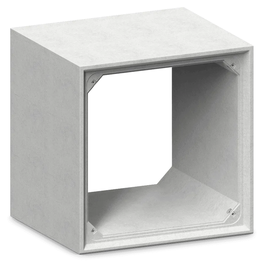
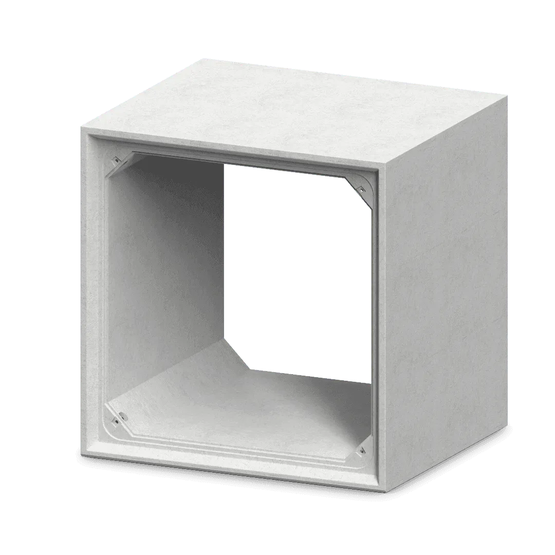
Box culvert: a precast RCC unit, a closed rectangular concrete segment with haunched inner corners (3D render)
01 Standard sizes
25
02 Inner B × H
300 × 300 to 2500 × 2500 mm
03 Concrete grade
M50–M75
04 Joint
Plug & socket + gasket
Scroll
[01]The unit

Box culvert, every detail

One closed RCC segment: top slab, bottom slab and two side walls cast together, with a plug at one end and a socket at the other. Here are its key facts; the full dimension table for all 25 sizes, the drawings and the 3D configurator are on the technical sheet.

Precast RCC box culvert unit
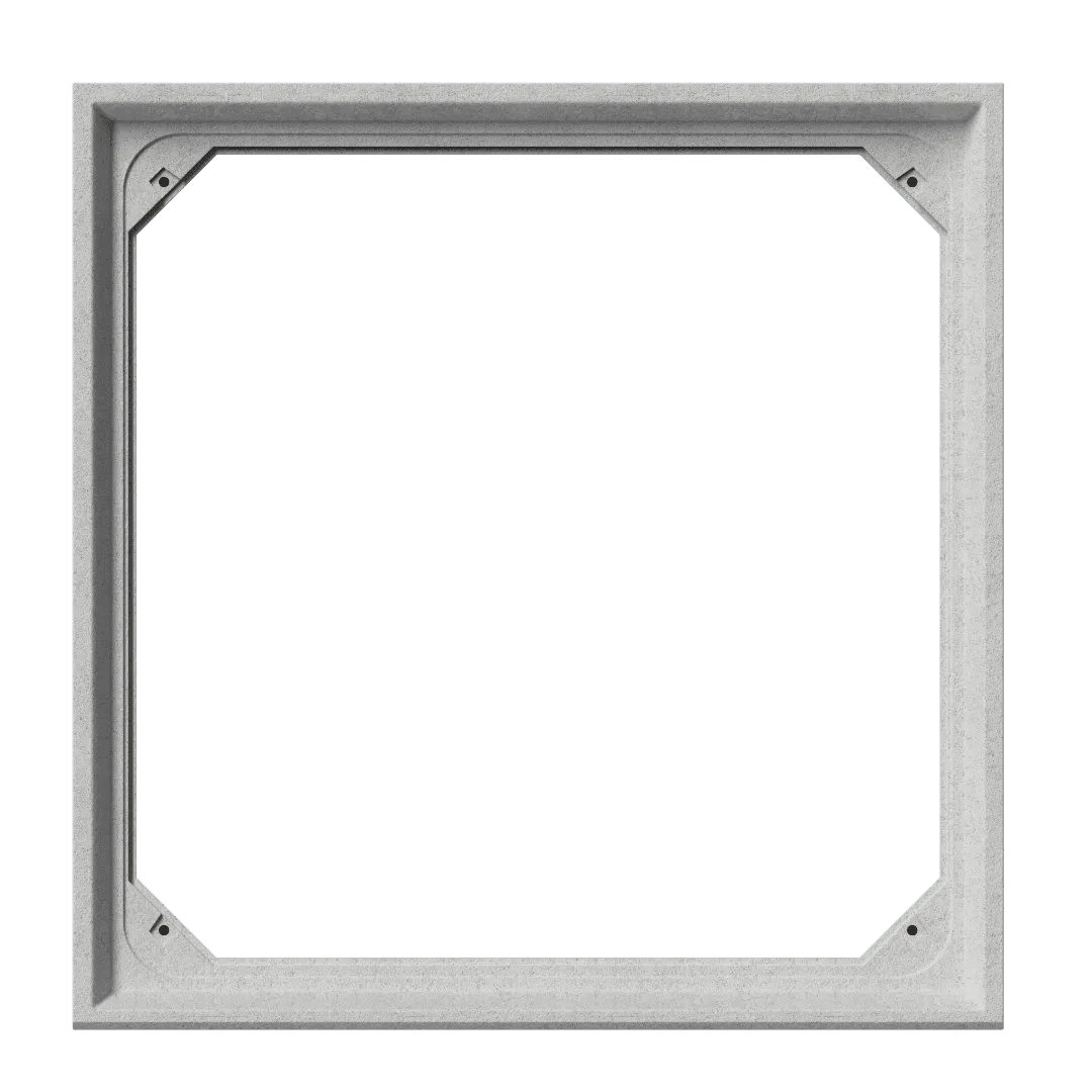
Precast RCC box culvert end view: the square opening with haunched inner corners
Precast RCC box culvert in three-quarter view, looking into the closed rectangular opening

Box Culvert

Reinforced precast RCC box culvert built for heavy-load cross-drainage under roads, highways, railways, and flood-prone infrastructure corridors.

25 sizes · 300 × 300 to 2500 × 2500 mm (clear B × H)

Size range
300 × 300 to 2500 × 2500 mminner B × H
Standard sizes
25
Unit length L
2000 / 1500 mm1500 mm for B 2500
Concrete grade
M50–M75
Joint
Plug & socketflange bolt: selected sizes
Sealing
Rubber gasket

Durable Material

Manufactured with M50 to M75 grade RCC and reinforcement steel.

Efficient Design

Closed rectangular profile allows high-volume water passage while supporting road or rail traffic above.

Dual Application

Used for cross-drainage under highways, railways, irrigation canals, and flood diversion channels.

Applications

  • Storm water drains
  • Power ducts
  • Road crossings
  • Replacement of pipe culverts
[02]By the numbers
  • 25

    Standard sizes

    inner B × H

  • M50–M75

    Concrete grade

    precast RCC, every unit

  • 300–2500mm

    Inner span B and height H

  • 3

    Foundation rows by span

    t1 100–200 / t2 150–250 mm

  • 2000mm

    Unit length L

    1500 mm for B 2500

  • 2005

    Precast in Surat since

    Trilok Infratech

[03]Sizes

Box culvert sizes

A size names the clear opening, inner span B × inner height H, not the outside. Enter the opening you need: the smallest standard box that covers it lights up in both charts, and the anatomy drawing below redraws to match.

Size explorer

Set the clear opening you need — the smallest standard size that covers it lights up below.

Standard precast box culvert sizes: inner span B × inner height H (mm)
Span B (mm)H 300H 500H 600H 800H 1000H 1200H 1400H 1500H 1800H 2000H 2500
B 300300 × 300
B 500500 × 500
B 600600 × 600600 × 1000
B 800800 × 800800 × 1400
B 900900 × 1000900 × 1400
B 10001000 × 6001000 × 10001000 × 1400
B 12001200 × 10001200 × 1400
B 13001300 × 1400
B 14001400 × 10001400 × 1200
B 15001500 × 1400
B 20002000 × 12002000 × 15002000 × 18002000 × 2000
B 25002500 × 15002500 × 18002500 × 20002500 × 2500
Customized sizes available for mass quantity.
Precast box culvert sizes at a glance: outer size, unit length, slab and wall thickness (mm)
B × H (mm)B1 outer widthH1 outer heightL unit lengthTS slabTW wall
300 × 300416475200095/8055
500 × 500680740200012090
600 × 600775860200013080
800 × 800106010602000130130
600 × 100086012602000130130
900 × 1000116012602000130130
1000 × 1000126012602000130130
1200 × 1000146012602000130130
1000 × 60012608602000130130
800 × 1400106016602000130130
900 × 1400116016602000130130
1000 × 1400126016602000130130
1200 × 1400146016602000130130
1300 × 1400156017002000150130
1500 × 1400176017002000150130
1400 × 1000166012602000130130
1400 × 1200166014602000130130
2000 × 1200232015602000180160
2000 × 1500232018602000180160
2000 × 1800232021602000180160
2000 × 2000232023602000180160
2500 × 1500290019401500220200
2500 × 1800290022401500220200
2500 × 2000290024401500220200
2500 × 2500290029401500220200
All dimensions in mm. Joint: Plug & Socket Joint; Flange Bolt Connection (available for selected sizes); Sealing Material - Rubber Gasket.

The brochure also prints 900 × 900, 1200 × 1200, 1500 × 1500 and 3000 × 3000 mm as additional sizes (confirm availability). Customized sizes available for mass quantity.

[04]Anatomy

Anatomy of a precast RCC box culvert

Pick any of the 25 standard sizes. The drawing redraws itself to scale from the published table: the opening, the outside, slabs, walls, corner haunches, the plug and socket ends, and the foundation under it.

B × H1000 × 1000mm

Front viewSection through the barrel
Box culvert front view, drawn to scale from the published dimensions of the selected size
Side viewPlug end · socket end
Box culvert side view at the same scale: unit length L, plug end offset d1 and socket end offset d2
BInner span
1000 mmInner clear width (span) of the opening, between the inside faces of the two side walls.
HInner height
1000 mmInner clear height of the opening, between the top and bottom slabs.
B1Outer width
1260 mmOverall outer width of the box across both side walls.
H1Outer height
1260 mmOverall outer height of the box across both slabs.
LUnit length
2000 mmUnit (laying) length of one precast segment along the barrel.
TSSlab thickness
130 mmSlab thickness: the top and bottom slabs are both labelled Ts in the front view.
TWWall thickness
130 mmSide wall thickness: both side walls are labelled Tw in the front view.
CCorner haunch
150 mmSize of the internal corner haunch (45° chamfer at the inside corners of the opening), drawn with equal horizontal and vertical legs C in the front view.
d1Plug end
60 mmSmall axial offset at one end of the unit in the side view, outside the L dimension; appears to be the projection of the plug (spigot) end of the plug & socket joint.
d2Socket end
60 mmSmall axial step at the opposite end in the side view; appears to be the depth of the socket recess that receives the next unit's plug.

Foundation under this size

20 bedding mortart1 100 concretet2 150 crushed stoneB2 1460 wide

From the published foundation table (span 600 ~ 1000); B2 = B1 + 100 mm each side.

View in 3DAll dimensions
Box culvert slab (TS) and wall (TW) thickness by size (mm)
TS slab (mm)TW wall (mm)Sizes B × H (mm)
95/8055300 × 300
12090500 × 500
13080600 × 600
130130800 × 800 · 600 × 1000 · 900 × 1000 · 1000 × 1000 · 1200 × 1000 · 1000 × 600 · 800 × 1400 · 900 × 1400 · 1000 × 1400 · 1200 × 1400 · 1400 × 1000 · 1400 × 1200
1501301300 × 1400 · 1500 × 1400
1801602000 × 1200 · 2000 × 1500 · 2000 × 1800 · 2000 × 2000
2202002500 × 1500 · 2500 × 1800 · 2500 × 2000 · 2500 × 2500
As published: the thickness steps up with the opening.
[05]Joints

How box culvert units join

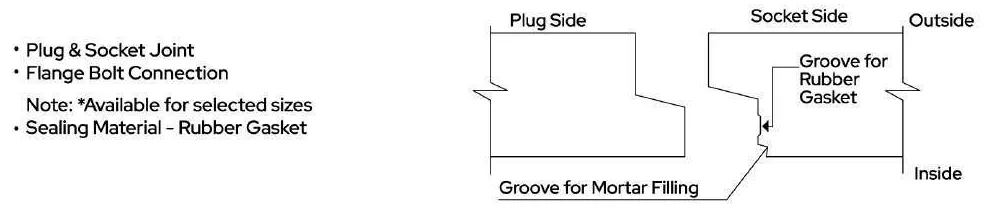
Every unit has a plug end and a socket end. The plug of each new unit slides into the socket of the last, which keeps the barrel in line while a rubber gasket seals the gap. Scroll to close the joint.

Schematic section through a box culvert wall at the joint: the plug side of one unit engages the socket side of the next, with a rubber gasket groove and a mortar groove
Schematic of the published joint detail, not to scale.
  1. Plug & socket joint

    The plug end of each unit slides into the socket end of the next, so the units lock into one straight barrel.

  2. Rubber gasket

    Seated in its groove, the gasket is squeezed as the joint closes and seals it.

  3. Mortar groove

    A second groove at the inside face of the joint takes mortar filling.

  4. Flange bolt connection

    Available for selected sizes, where units are also bolted together across the joint.

  5. Why joints matter

    A sealed joint keeps water inside the barrel and stops the backfill from washing in through the gaps, which could otherwise leave voids around the box.

Box culvert joint detail drawing: Typical joint details: plug side and socket side section with groove for rubber gasket and groove for mortar filling. Plug & socket joint, flange bolt connection (selected sizes), rubber gasket sealing.
Typical joint details: plug side and socket side section with groove for rubber gasket and groove for mortar filling. Plug & socket joint, flange bolt connection (selected sizes), rubber gasket sealing.
Box culvert joint offsets d1 (plug end) and d2 (socket end) by size (mm)
d1 / d2 (mm)Sizes B × H (mm)Sizes
Not published300 × 300 · 500 × 500 · 600 × 6003
60 / 60800 × 800 · 600 × 1000 · 900 × 1000 · 1000 × 1000 · 1200 × 1000 · 1000 × 600 · 800 × 1400 · 900 × 1400 · 1000 × 1400 · 1200 × 1400 · 1300 × 1400 · 1500 × 1400 · 1400 × 1000 · 1400 × 120014
80 / 802000 × 1200 · 2000 × 1500 · 2000 × 1800 · 2000 × 2000 · 2500 × 1500 · 2500 × 1800 · 2500 × 2000 · 2500 × 25008
As printed in the dimension table. Flange bolt connection available for selected sizes.
[06]Foundation

Box culvert foundation & bedding

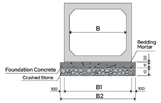
Under each unit (spans from 600 mm): 20 mm bedding mortar, foundation concrete t1 and crushed stone t2, on a foundation 100 mm wider than the box on each side. Read t1 and t2 from your span B.

Box culvert foundation by span B: foundation concrete t1 and crushed stone t2 (mm)
Span B (mm)t1 foundation concretet2 crushed stone
600 ~ 1000100150
1100 ~ 2000150200
2200 ~ 3000200250
All dimensions in mm. The box sits on 20 mm bedding mortar over foundation concrete (t1) and crushed stone (t2); foundation width B2 = B1 + 100 mm each side.
Box culvert foundation detail drawing: Typical foundation detail: box on 20 mm bedding mortar over foundation concrete (t1) and crushed stone (t2); foundation width B2 = B1 + 100 mm on each side.
Published typical foundation detail

How to read it

  1. Find your span B in the left column: B is the inner clear width of the box.
  2. Stack the layers under the box: 20 mm bedding mortar, then t1 foundation concrete (100–200 mm), then t2 crushed stone (150–250 mm).
  3. Size the foundation width B2 = B1 + 100 mm on each side, where B1 is the outer width of the box.
  4. Smaller spans: the table starts at B 600, so no row is published for 300 × 300 or 500 × 500. Ask us for site guidance.

The anatomy drawing above shows the foundation for the size you pick. The project engineer's design always governs.

[07]Installation

How a precast box culvert is installed

Excavation to backfill in eight steps. The units arrive cured from the yard, so the work at the crossing is mostly foundation, lifting and jointing.

Backfill in even layersExcavation to line & levelPlug & socket + gasketBox culvert unit20 mm bedding mortarFoundation concrete t1 · 100–200 mmCrushed stone t2 · 150–250 mm
Typical foundation detail, as published: t1 and t2 by span in the foundation table. Schematic · not to scale
  1. Step 1: Set out & excavate

    Mark the line and levels from the drawings and excavate wide enough for the foundation, which runs 100 mm beyond the box on each side (B2 = B1 + 100 mm each side).

  2. Step 2: Crushed stone (t2)

    Lay and compact the crushed stone layer: t2 is 150–250 mm, by span, in the foundation table.

  3. Step 3: Foundation concrete (t1)

    Cast the foundation concrete to line and level: t1 is 100–200 mm, by span.

  4. Step 4: Bedding mortar

    Spread the 20 mm bedding mortar just ahead of each unit so it beds down evenly.

  5. Step 5: Lift & place

    Crane each unit onto the bed in sequence, checking line and level as it lands.

  6. Step 6: Close the joint

    Seat the rubber gasket in its groove, then push the plug of the next unit fully into the socket of the last, and fill the mortar groove as the drawings require.

  7. Step 7: Check the run

    Check line, level and joint gaps along the whole run before any backfill goes in.

  8. Step 8: Backfill evenly

    Backfill both sides together in compacted layers, then over the top, so the box is never loaded from one side only.

General sequence for guidance only. Always follow your project drawings and the engineer's specification.

[08]Applications

Where box culverts work

Wherever water, cables or services must pass under a road, railway or embankment.

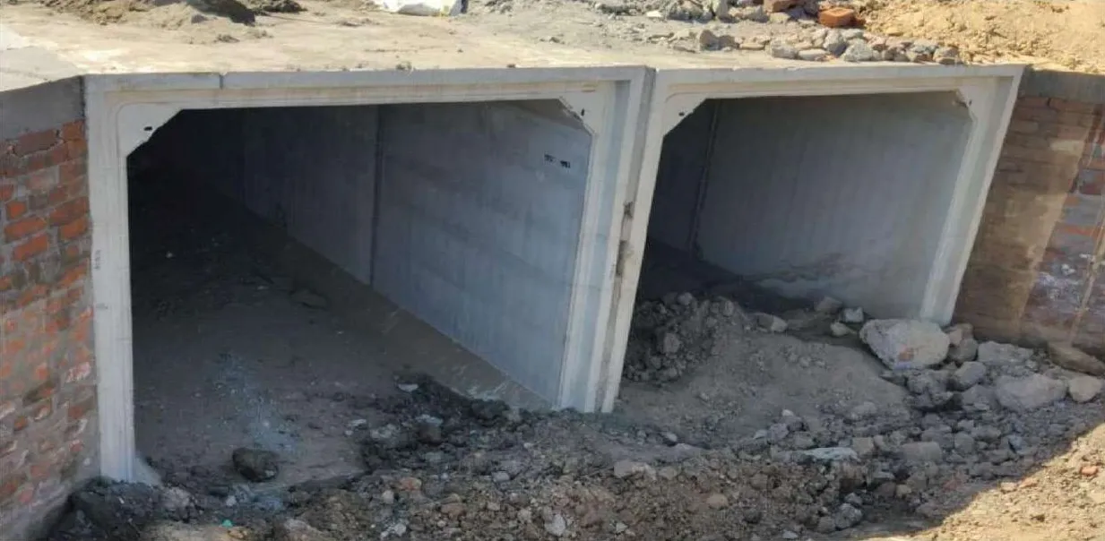
  • An installed twin-cell precast box culvert set between brick walls, its openings partly filled with soil and rubble
    Site photo · Trilok Infratech
    Drainage

    Storm water drains

    Carries storm water under roads, plots and yards in one closed, continuous barrel. Openings run from 300 × 300 to 2500 × 2500 mm, so a small outfall and a wide drain crossing use the same system.

  • Crossing

    Road crossings

    Closed rectangular profile allows high-volume water passage while supporting road or rail traffic above.

  • Corridors

    Highways, railways & canals

    Used for cross-drainage under highways, railways, irrigation canals, and flood diversion channels.

  • Services

    Power ducts

    A closed box gives cables and service lines a protected corridor under roads and yards, jointed unit to unit with plug & socket joints.

  • Upgrade

    Replacement of pipe culverts

    Where a pipe crossing is too small or worn out, a box uses the full width and height of the opening, which helps where the road sits only a little above the channel.

[09]Culvert types

Box culvert vs pipe culvert vs slab culvert

Box, pipe and slab culverts carry water across a road; a U drain carries it along one. How the four compare, in plain terms.

Box culvert vs pipe culvert vs slab culvert vs U drain (general comparison)
AspectBox culvertPipe culvertSlab culvertU drain (open channel)
Cross-sectionClosed rectangle: top slab, bottom slab and two side walls in one unitClosed circle: one or more round pipesFlat deck slab resting on two side walls (abutments)Open U-shaped channel, with or without covers
RunsAcross the line: under a road, railway or embankmentAcross the line: under a road or embankmentAcross the line: under a roadAlong the line: beside a road, plot or yard
Shape advantageUses the full width and height, so a wide, low opening fits where there is little height between bed and roadSimple to lay; for the same flow area a round pipe is taller than a wide box, so pipes are often laid side by sideWide openings on firm ground; the bed under the deck can stay naturalEasy to inspect and clean; covers turn it into a closed trench
Load on the groundThe bottom slab spreads the load across the whole width of the boxEach pipe bears on its own beddingThe walls carry the deck on their own foundationsThe base of the channel spreads the load
Typical buildPrecast units placed and jointed, or cast in placePrecast pipes placed and jointedUsually cast in place: walls first, then the deck slabPrecast units laid end to end in a trench
On this site25 standard sizes, 300 × 300 to 2500 × 2500 mmNot listed on this siteNot listed on this siteU Shape Drains: T25 · T6 · FT
General comparison for orientation only. The right type for a crossing comes from its hydraulic and structural design.
[10]Precast vs cast-in-situ

Precast or cast on site?

A general comparison of the two ways to build a box culvert.

Precast box culvert vs cast-in-situ box culvert (general comparison)
AspectPrecast box culvertCast-in-situ box culvert
Where it is castIn factory moulds, cured in the yard before dispatchFormed, reinforced and poured at the crossing
Quality controlThe same moulds, mix and curing routine for every unitDepends on site formwork, weather and curing
Work at the crossingFoundation, then units lifted in and jointedFoundation, formwork, steel fixing, pouring, curing, stripping
Road or channel closed forUsually shorter: the barrel arrives finishedUsually longer: until the concrete has gained strength
EquipmentCrane and trucksFormwork, props and a concrete supply
JointsPlug & socket joint at every unit (L 2000 / 1500 mm), rubber gasket sealConstruction joints where the pours meet
Sizes25 standard sizes, 300 × 300 to 2500 × 2500 mm; customized sizes available for mass quantity.Any size or shape formed on site
SuitsRepeat crossings, short closures, sites with crane accessVery large or irregular one-off structures
[11]On site

Cast in Surat, proven on site

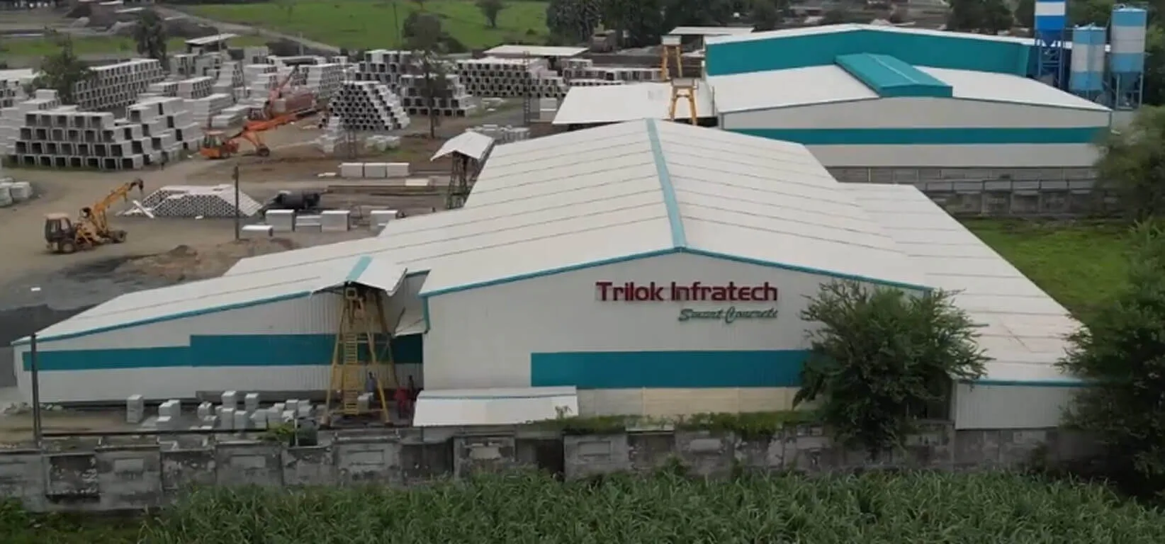
Cast at the Trilok Infratech factory near Surat. The company has made precast RCC since 2005 and supplies clients in 3 countries, including 18 states of India.

As per our Requirement for Vistara Industrial Park Savli – Located in Tundav, We Needed Box Culvert 1000x1000 of 36 RMT, as we given PO (VRL/VIPS/PO/2026/0062) we have Received material Quality Ok form our Side, Also within Timeline as schedule, Refer to purchase precast material from Trilok Infratech PVT LTD for Good Quality, Under Timeline Delivery, Smoothen Payment System.

Vistara Realty
Aerial view of the Trilok Infratech precast plant: a white-and-teal factory shed signed “Trilok Infratech – Smart Concrete”, with a yard of stacked precast units, a crane, loaders and cement silos behind it
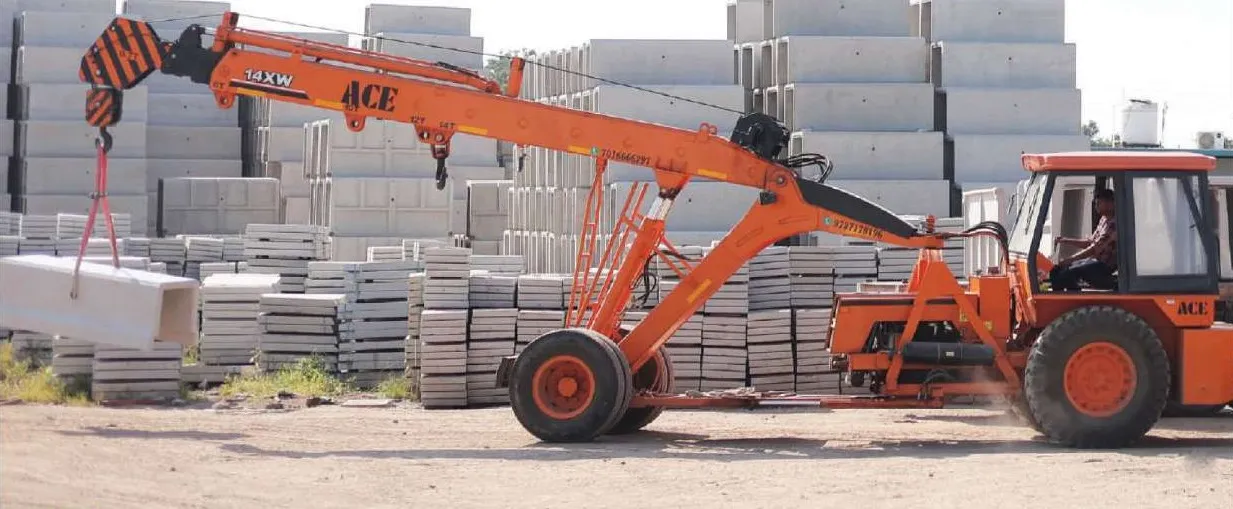
An orange ACE pick-and-carry crane lifts a precast concrete unit in the stockyard, with tall stacks of precast U-drains and cover slabs behind
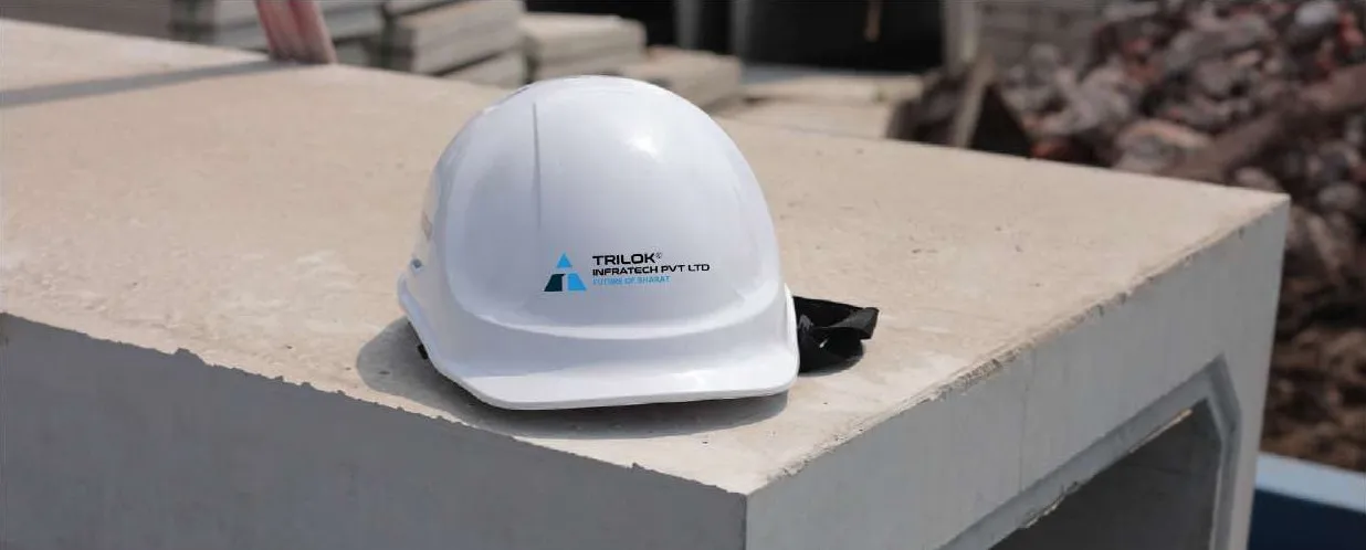
A white hard hat bearing the Trilok Infratech logo resting on top of a precast concrete box unit
[12]Price

Box culvert price: what affects it

We quote every job on its sizes and scope. These are the things that move the number.

  1. Size & thickness

    A bigger box puts more concrete and steel into every unit, and TS / TW step up with the span: 130 / 130 mm at 1000 × 1000, 180 / 160 mm at 2000 × 2000, 220 / 200 mm at 2500 × 2500.

  2. Unit length & joints

    2000 mm for 300 × 300 to 2000 × 2000 and 1500 mm for 2500 × 1500 to 2500 × 2500: the length sets how many units, lifts and joints a run needs. Plug & socket with a rubber gasket as standard; flange bolt connection for selected sizes.

  3. Quantity

    Customized sizes available for mass quantity. Quantities also set the casting and dispatch plan.

  4. Foundation works

    Crushed stone (t2), foundation concrete (t1) and 20 mm bedding mortar under each unit (published for spans from 600 mm).

  5. Transport & lifting

    Distance from the Surat factory, units per truck and crane access at the crossing.

[13]FAQ

Box culvert questions

  1. A box culvert is a closed rectangular concrete conduit that carries storm water, canal flow or services under a road, railway or embankment. Trilok Infratech casts them in M50–M75 precast RCC at Surat, in 25 standard sizes from 300 × 300 to 2500 × 2500 mm (B × H), with plug & socket joints sealed by rubber gaskets.

  2. To carry water or services under a road, railway or embankment: storm water drains, power ducts, road crossings and replacement of pipe culverts. Used for cross-drainage under highways, railways, irrigation canals, and flood diversion channels.

  3. A box culvert is one closed rectangular unit (top slab, bottom slab and two side walls cast together), so its bottom slab spreads the load across the full width and a wide, low opening fits where there is little height between the bed and the road. A pipe culvert uses round pipes: simple to lay, but for the same flow area a pipe is taller, so several are often laid side by side. A slab culvert is a deck slab resting on two walls with their own foundations, usually cast at site.

  4. Trilok Infratech lists 25 standard sizes from 300 × 300 to 2500 × 2500 mm, named inner span B × inner height H: spans B 300, 500, 600, 800, 900, 1000, 1200, 1300, 1400, 1500, 2000 and 2500 mm with heights H from 300 to 2500 mm. The brochure also prints 900 × 900, 1200 × 1200, 1500 × 1500 and 3000 × 3000 (confirm availability). Customized sizes available for mass quantity.

    Derived from spec tablesOpen the size chart →
  5. It grows with the opening. Side walls (TW) run from 55 mm on the 300 × 300 to 200 mm on the 2500 × 1500, 2500 × 1800, 2500 × 2000 and 2500 × 2500 sizes, and the slabs (TS) reach 220 mm on the 2500 × 1500, 2500 × 1800, 2500 × 2000 and 2500 × 2500 sizes. Examples: 300 × 300: TS 95/80 / TW 55 mm; 1000 × 1000: TS 130 / TW 130 mm; 2500 × 2500: TS 220 / TW 200 mm.

    Derived from spec tablesDraw any size to scale →
  6. The unit (laying) length L is 2000 mm for 300 × 300 to 2000 × 2000 and 1500 mm for 2500 × 1500 to 2500 × 2500.

    Derived from spec tables
  7. With a plug & socket joint: the plug end of each unit slides into the socket end of the next. A rubber gasket, seated in its groove, seals the joint, and the joint detail has a second groove for mortar filling. A flange bolt connection is available for selected sizes.

    Derived from spec tablesSee how the joint closes →
  8. The published detail: the box sits on 20 mm bedding mortar over foundation concrete (t1) and crushed stone (t2), on a foundation 100 mm wider than the box on each side (B2 = B1 + 100 mm each side). By span B: 600 ~ 1000 mm: t1 100 / t2 150 mm; 1100 ~ 2000 mm: t1 150 / t2 200 mm; 2200 ~ 3000 mm: t1 200 / t2 250 mm. No foundation row is published for 300 × 300 and 500 × 500. The project engineer's design always governs.

    Derived from spec tablesFoundation table →
  9. M50–M75 grade reinforced cement concrete, for every size. Manufactured with M50 to M75 grade RCC and reinforcement steel.

  10. No load rating or wheel-load class is published for the box culvert. Share your design loading, the cover depth over the box and the site details with the enquiry, so the size can be confirmed for your crossing.

  11. Prices are quoted per job, not published. The main factors are the size and its slab and wall thickness, the unit length (2000 / 1500 mm), the joint type, the quantity (customized sizes available for mass quantity), the foundation works, and transport and lifting from Surat. Call +91 95104 39933 or email sales@trilokinfratech.com for a quotation.

  12. They are cast at the Trilok Infratech factory, Survey No. 18, NH-8 to Velanja Road, Taluka Kamrej, Village Antroli, Surat, Gujarat 394150. The company has made precast RCC products in Surat since 2005 and supplies clients in 3 countries (India, Senegal and Ecuador), including 18 states of India.

Get a box culvert quote

Add to your enquiry slip

—Mon to Fri 10:00am - 7:00pm · Saturday 10:00am - 2:00pm · Sunday Closed